Replacing Duct Burners in Combined Cycle Power Plants

Many combined cycle power plants (CCPP) and cogeneration or combined heat and power (CHP) plants utilize supplemental firing systems, or duct burners, inside the heat recovery steam generator (HRSG) boilers. Duct burners can be activated on demand to rapidly and efficiently increase the HRSG steam output to the steam turbine generator for added megawatts in CCPPs, where megawatt output can be on-demand or preplanned from the producer’s applicable dispatch to support demand for electricity. Duct burners can also increase steam output for customer use, ultimately delivering higher sales for the CHP producer.
Across the domestic market, many duct burners were installed in original greenfield CCPPs and cogen/CHPs built between 1995 and 2005. Duct burner installations slowed in greenfield CCPPs and cogen/CHPs between 2005 and 2015. Since 2015, construction of new CCPP and cogen/CHP facilities has nearly stalled due to the economy and recent pressure from governmental agencies to research and invest in green fuel technologies. As a result, power plant infrastructure across the domestic market is aging and needs attention.
Unfortunately, due to the aging of existing equipment infrastructure, many duct burner systems in place today have reached or are rapidly approaching their designed end-of-life cycle and present a range of issues for the producer, such as:
- Increasing maintenance costs to repair equipment continually
- Increasing operational costs with higher emissions or flame impingement on the HRSG
- Partial failure of the burners, creating light-off and reliability issues
- Complete failure of the burners, resulting in problems as simple as burners rendered non-functional and as complex as burners collapsing to the HRSG floor
- Continued decay of aging equipment at exponential rates over time

Frequent documented inspections and supervisory monitoring of aging equipment are vital in understanding the current condition of a facility’s duct burners and knowing when capital cost budgeting should be in place for repairs or replacement. Inspections can be performed while equipment is in operation but are best performed during outages, typically during the spring and fall, and should be performed by a reputable combustion company. These inspections can identify issues that may impact existing equipment, diagnose why failures have already happened, and determine whether replacement is more economical than continued maintenance. Inspections can be completed in as little as one day if coordinated appropriately so as not to delay restarting the facility.
Replacement of duct burner systems is often easier than most producers realize. This can be the best approach to preserve the lifecycle of power production capabilities because replacement stops the aging process and resets the clock for the producer, eliminating one of many worries for the management team. This case study of one such turnkey duct burner system (Figure 1) replacement performed by Zeeco helps facility owners understand the pathway from diagnosis to start-up and demonstrates the benefits of eliminating aging equipment from a power plant’s infrastructure.
The Situation
In 2022, a major electric-producing utility in the southeastern U.S. contacted Zeeco with concerns about its existing duct burner system. Zeeco performed an outage inspection and recorded findings, which included:
- Badly warped flame stabilizers
- Pilot light failure for the main fuel flame of the burner element
- Poor flame scanner recognition
- Flame impingement on the downstream HRSG tube section
Warped and distorted flame stabilizers can result from the inability to control the flame shape due to poor turbine exhaust gas (TEG) flow. This is generally caused by older designs that were always inadequate but unknown until the introduction of newer technologies. The simple aging process of combustion equipment subjected to years of cycling on and off also wears out flame holders and bluff bodies. In this case, both were noted as contributors to equipment decay.
The inability of the pilot to light off the main fuel flames can result from sagging burner elements. Additional causes for this failure are simply the destruction of the sparking device(s) that reside inside the HRSG furnace environment day after day at extreme temperatures. The general electrical circuitry of high-energy ignition systems is easily disrupted by water vapor from the TEG and open conduit systems, which can often be soaked with stormwater. In this case, the sagging of the burner element was the primary cause of the pilot’s failure to light the main fuel. The sparking tips were no longer in the path-way of the main fuel and never stood a chance to light.
Poor flame scanner recognition of the main fuel flame can also be attributed to several issues:
- Sagging burner elements.
- Dirt, debris, or water vapor coating the lens of the flame scanner.
- Unintended movement of the flame scanner mounting system due to the normal heavy vibrations of the HRSG.
- Older scanner models using outdated flame recognition algorithms that cannot properly discern flame versus no flame.
Electronic components do not last forever and can easily cause poor flame recognition.
.jpg?width=589&height=448&name=Picture1%20(1).jpg)
In this case, the scanners were old technology and had worn out in various stages across the multiple burner elevations.
Flame impingement on the downstream HRSG tube section is the leading destroyer of HRSG boilers, costing millions to repair those long alloy boiler tubes. Long, lazy flames create flame impingement as the burner system introduces raw fuel into the HRSG furnace (under full control of the burner management system [BMS]) and is ignited by the pilot igniter. Once the main fuel flame is on and recognized by the flame scanner, the HRSG distributed control system (DCS) allows fuel to be ramped up to meet output steam demand.
However, as the burner tips erode under fuel pressure over time, or flame stabilizers warp due to recirculation of TEG flow and burner flame, or as burner elements sag (Figure 2), the fuel is allowed to flow further downstream of the burner tip before actual or complete combustion takes place. These factors can enable flames to grow longer until they impinge on the tubes. Over time, impingement will destroy the tubes. This issue must be corrected, or future failure is imminent. In this case, longer flames caused by eroded burner tips contributed to flame impingement.
The Challenge
This project included both common and situationally specific challenges. Specifically, the pre-planned outage was scheduled for 18 days in the spring and was classified as a non-major outage, meaning that no combustion turbine or steam turbine modifications were planned to be completed during this outage. Outages are commonly planned far in advance at many sites, making it very important to understand the existing condition of duct burner equipment so that replacement can be completed without interrupting or altering existing pre-planned outage schedules.
The customer further explained that this facility was critical to the grid in that the demand for steam production and megawatt output was of the highest importance due to the massive customer base. Missing the outage timing was not an option, and the unit had to be operational on the last day of the outage. The next planned outage for this site was not for several years, adding another important consideration to the equipment and the installation. Extensive turnkey planning was required to meet this timing challenge, and constant communication with the facility was critical.
Commonly, the design and installation must fit within the pre-approved capital budget cost value of the outage. In this case, the customer had a capital budget approved roughly two years before the purchase of the new burners. However, inflation within the economy and the re-cent pandemic caused material pricing to be an unforeseen concern.
Timing of the request for quotation versus the installation outage dates was key to success. Design, fabrication, delivery, and installation each consume a number of weeks out of the overall schedule to perform success-fully. Therefore, it was crucial to order the equipment well before the planned outage schedule. Again, understanding the existing condition of the duct burner equipment allowed the facility owner to plan the replacement properly.
Project Process
The design for the retrofit was completed by a highly experienced team that has performed numerous successful duct burner turnkey replacement projects, along with greenfield duct burner designs and fabrication for an extensive list of original equipment manufacturers worldwide. Keeping one team of engineers and managers on the project strengthens relationships with the customer team and eliminates information gaps across the project.
Material purchases were completed by personnel trained extensively in finding the best pricing and delivery. Zeeco utilizes an extensive approved manufacturer list monitored by its International Organization for Standardization, or ISO, program, which gives tremendous purchasing power to the buyers involved and eliminates the need for concern regarding new or un-tested suppliers.
Fabrication of the equipment in one of Zeeco’s seven global manufacturing facilities was heavily monitored by the Quality Assurance/Quality Control (QA/QC) team and the project execution engineering team. Delivery was planned and performed by a logistics team of transportation experts. Prior to the project execution phase, Zeeco created a highly specific turnkey task-by-task outline and plan for all mechanical and electrical work that was to be performed onsite. The implemented plan was followed by experienced construction crews.
Discovery
Nearly all turnkey installation projects produce some discovery that identifies unknown issues before the start of the demolition of the existing equipment. In the case of this project, the discovery was serious internal corrosion to the HRSG carbon steel casing walls (Figure 3). This type of discovery is increasingly common for older HRSG and duct burn-er equipment, specifically when HRSG units are originally installed near ma-rine environments or in places where temperature extremes may cause the exposed casing, enclosed HRSG wall insulation, and the HRSG internal float-ing liner plate system to work extraordinarily hard.
Other common discoveries for these types of HRSGs and duct burners are internally corroded fuel piping, reduced wall thicknesses of the pressure piping, and valve seat corrosion or destruction. These issues develop over time due to varying fuel temperature fluctuations throughout the plant’s fuel piping infrastructure caused by changing weather and seasonal conditions. The external piping was already scheduled for replacement for this project with new corrosion-free piping, fittings, and valves.
The Solution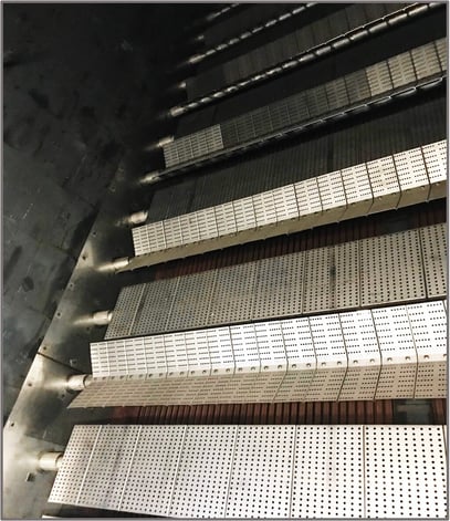
This turnkey duct burner replacement project was planned to keep in mind those common types of discovery. Each potential discovery is discussed with the customer before finalizing the purchase of equipment and turnkey installation. Mitigating discoveries upfront through detailed planning creates a performance schedule that is as accurate as possible to real-world scenarios and helps eliminate surprises.
During a planned outage, other contractors are often onsite performing work on other equipment, such as the cooling towers or boiler drum belly pans and relief valves. The site can become congested, and tool trailers and construction office spaces can reduce material staging zones. Using a reputa-ble installation company and ensuring daily attendance to outage meetings offers all contractors the ability to voice and share concerns and look-ahead plans daily. Coordination among contractors can avoid issues like competition for a crane or overhead lift spaces and non-destructive examination radiographic testing examination clearances, as well as road congestion due to material and consumables delivery. A well-communicated project is a safer project, eliminating accidents and potentially saving lives.
Outcomes and Benefits
Following the startup of this project and the demobilization of the installation crew, the benefits to this customer were very clear. Each of the following points satisfied the customer’s needs and brought much-needed life back to the duct burner system for many years.
Turnkey Success
The duct burner replacement was completed in 16 days instead of the allotted 18, allowing for the successful reignition of the unit on the final day of the outage.
Cost
In this case, Zeeco’s global purchasing power allowed the team to source materials and saved the original capital budget value created far in advance of the equipment purchase.
New Equipment
The customer now has a new duct burner system without any of the previous problems. Financial savings from reduced maintenance and operation costs will result in savings over time.
Correct Equipment
The design and the installation were 100% compliant with the specification, meaning the customer received everything they asked for within one outage and under one budget cost.
Heat Release
The new equipment delivers the proper amount of heat release into the HRSG boiler for optimal steam production.
Fabrication
Zeeco utilized one of seven in-house global manufacturing facilities to complete the equipment on time and within full compliance with both the company’s internal and the customer’s QA/QC requirements.
Delivery
Knowing that the purchased equipment would be delivered to the site utilizing the supplier’s logistics system saved many hours of customer management oversight and concern.
Installation
This turnkey installation utilized one of many mechanical and electrical installation teams that Zeeco uses and manages. A full turnkey installation also saved the customer many hours of management oversight and concern.
On-Time Performance
Project completion occurred earlier than anticipated and at the budgeted cost, benefiting the producer and ensuring that the planned outage was correct and no extension was necessary.
Zero Safety Incidents or Accidents
Everyone went home at the end of every day without injury. In the long term, insurance premiums remain low, the facility safety tracking metrics remain spotless, and the company’s safety record remains without blemish.
Improved Access
Less-congested access areas at the burner front allow for better maintenance and operations while also creating safer working environments.
Training
Getting the operations team trained on the new equipment from the supplier is vital to achieving flawless operations and reducing unnecessary trips.
Emissions
Having new equipment technology greatly reduces emissions in many cases and better enables operating companies to remain within their emissions tolerances.
Equipment Protection
Flame shape being well-anchored and flame lengths that fit well within the HRSG furnace eliminate damages to the downstream tube sections, liner walls, ceilings, and floor.
Compliance with National Fire Protection Association (NFPA)
NFPA 85, the governing body for duct burners, and Chapter 8 specifically, is commonly updated. Having new equipment means that the governing safeguards are already in place.
Warranty
New equipment provides limited warranties to the facility owners.